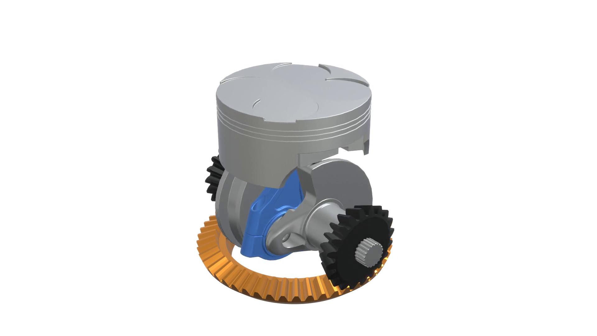
An axial bevel gear is a type of bevel gear that has teeth that are cut in an axial direction rather than a radial direction. It is used in applications where the input and output shafts are perpendicular to each other and intersect at a specific angle.
To create an axial bevel gear using an engine, you would typically follow these steps:
- Design the gear geometry: Determine the specifications of the gear, such as the number of teeth, the pitch diameter, the module (gear size), and the pressure angle. You can use specialized gear design software or CAD tools to create the gear geometry.
- Choose a suitable material: Select a material that has the required strength and durability for the gear application. Common materials for gears include steel, brass, and nylon, depending on the specific requirements.
- Manufacture the gear: Use CNC machining, gear cutting, or other manufacturing methods to produce the gear according to the designed geometry. This involves cutting the teeth in an axial direction to achieve the bevel gear shape.
- Assemble the gear: Install the axial bevel gear onto the respective shafts of the engine or machinery, ensuring proper alignment and engagement with other gears or components.
It’s important to note that designing and manufacturing gears, especially bevel gears, require expertise and precision. If you don’t have experience or access to specialized equipment, it may be advisable to consult a professional or a gear manufacturing company to ensure the gear meets the necessary specifications and quality standards.


